
Anupreethi
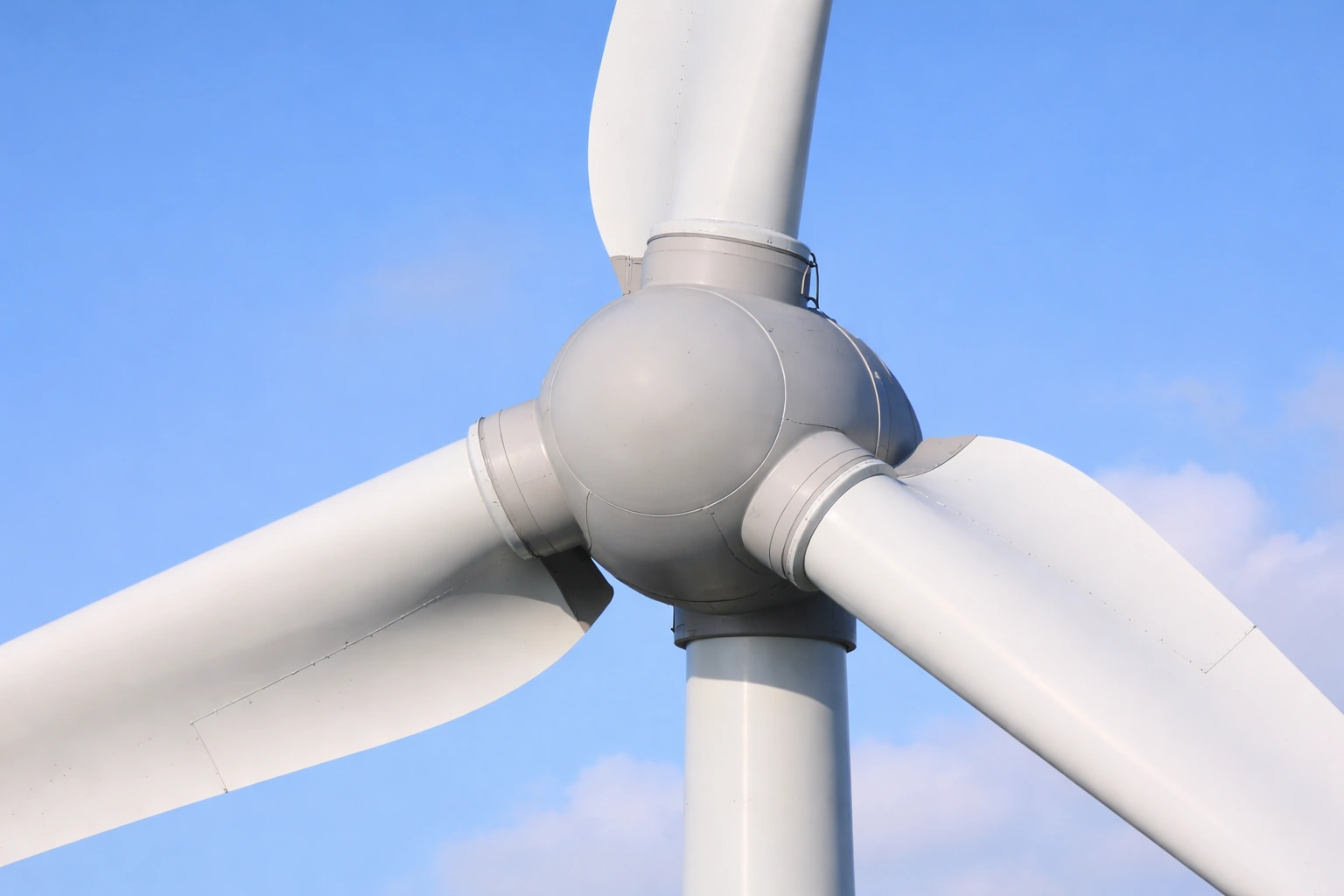
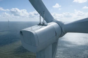
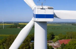
The rotor assembly is the primary energy capture system in a wind turbine. At the center of this system is the wind turbine rotor hub, which connects the blades to the drivetrain and transfers aerodynamic forces into rotational energy.
As turbine sizes increase across Europe, rotor diameters now exceed 150–200 meters, placing significant structural and mechanical demands on hub and spinner components. These elements must withstand high cyclic loads, maintain precise blade alignment, and ensure long-term fatigue resistance under varying wind conditions.
The rotor hub and spinner assembly therefore represents a critical intersection of structural engineering, casting technology, and system integration.
The wind turbine rotor hub serves as the central connection point for:
Its primary functions include:
Modern hubs are typically manufactured using large-scale castings or fabricated steel assemblies, depending on turbine design.
Engineering requirements include:
Structural inaccuracies in the rotor hub can result in uneven load distribution, leading to increased wear on pitch systems and drivetrain components.
The wind turbine rotor hub is one of the most complex components in terms of geometry and load-bearing requirements.
Manufacturing challenges include:
Cost and performance trade-offs:
Precision machining of flange interfaces and bearing seats is critical to ensure proper load transfer and rotational balance.
Unimacts supports wind turbine programs through fabrication and machining of structural components that contribute to alignment accuracy and integration readiness within rotor assemblies.
Each blade is mounted to the hub using pitch bearings, allowing rotation to optimise aerodynamic efficiency.
Integration requirements include:
Pitch systems must operate reliably under:
The wind turbine rotor hub must therefore provide both structural support and precise mechanical interfaces to enable smooth pitch operation.
The spinner—also known as the nose cone—is mounted at the front of the hub and serves both aerodynamic and protective functions.
Key roles include:
Spinners are typically manufactured from composite materials such as fiberglass or carbon-reinforced plastics.
Design considerations include:
Although not load-bearing, spinner design contributes to aerodynamic efficiency and protects sensitive hub components.
The rotor hub is subjected to:
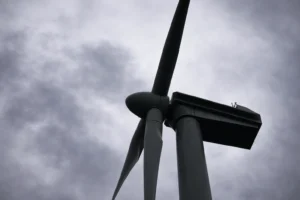
Fatigue performance is a critical design parameter, particularly for offshore turbines where maintenance access is limited.
Engineering approaches include:
Fabrication precision directly impacts load distribution and long-term durability.
Rotor balance is essential for turbine efficiency and component longevity.
Key factors include:
Imbalance can lead to:
Manufacturing processes must therefore ensure strict dimensional tolerances and quality validation.
Rotor hubs and spinners must be transported from manufacturing facilities to wind farm sites.
Challenges include:
Installation strategies may involve:
Fabrication planning must align with logistics to ensure efficient installation.
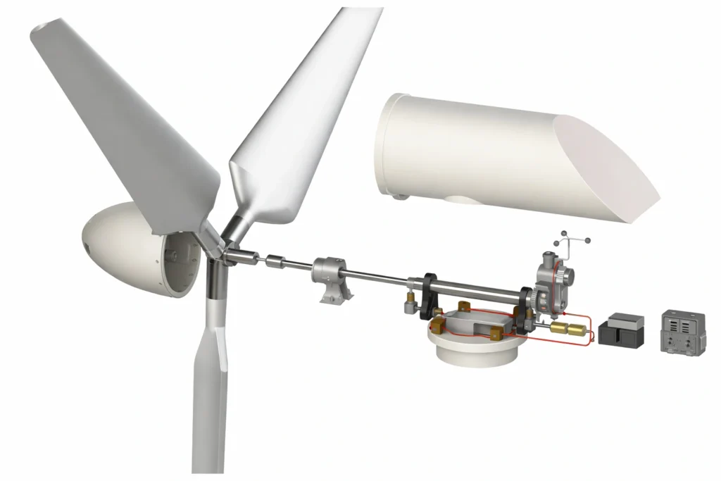
The wind turbine rotor hub connects directly to the main shaft, forming the interface between aerodynamic energy capture and mechanical power transmission.
Integration requirements include:
The hub must operate as part of a fully integrated system that includes:
Manufacturing accuracy ensures seamless integration and reduces commissioning challenges.
The wind turbine rotor hub and spinner assembly plays a central role in energy capture, load transfer, and system stability. As turbine sizes increase, the engineering complexity of these components continues to grow.
Structural precision, fatigue resistance, and integration accuracy define the performance of rotor systems. From hub casting and machining to spinner design and blade interface integration, each element must be engineered to operate under continuous dynamic loading.
Through precision fabrication, machining support, and structural component manufacturing, Unimacts contributes to wind turbine systems that prioritise alignment accuracy, durability, and integration readiness.
As Europe advances toward larger and more efficient turbine platforms, rotor hub engineering will remain a key determinant of turbine performance and lifecycle reliability.
1. What is a wind turbine rotor hub?
It is the central component that connects the blades to the main shaft and transfers aerodynamic forces into rotational energy.
2. What materials are used for rotor hubs?
Typically cast steel or fabricated steel, depending on turbine design and size.
3. What is the function of the spinner?
It improves aerodynamics and protects internal hub components.
4. Why is hub alignment important?
Proper alignment ensures balanced rotation, reduces vibration, and improves component lifespan.
5. Does Unimacts manufacture rotor hub components?
Unimacts supports structural fabrication and machining processes that contribute to rotor system integration and alignment.